Automotive Electronics Safety Webinar Highlights
By Evamaria Jones
In case you missed it, Lenora Clark hosted a very informative webinar on March 26th titled “Materials Considerations for Automotive Electronics Safety: Improving Reliability and Product Life to Achieve Next Level Autonomy.” Lenora Clark is the Director Autonomous Driving and Safety Technology at MacDermid Alpha and a chemistry scientist with 22 years of experience. Lenora Clark’s presentation is very impressive and inspired me to probe deeper into the material and put together the following Webinar highlights. This article is not intended to replace her presentation, for all the credit belongs to Lenora Clark. My hope is these highlights will encourage readers to watch the Webinar at https://youtu.be/o7UMK3fTReo. Also, any misrepresentations are not intentional; they are purely my interpretation.
The 1970s automobile was mostly mechanical in nature with little or no electronics. In today’s automobile, electronics control most every aspect of their various systems, including passive and active safety features. Amazingly, these active safety features such as blind spot detection, lane detection, and collision avoidance can prevent accidents. These features will be available in most cars in the future. Thanks to Auto Drive Assist Systems (ADAS), technology such as lidar, radar, and cameras has helped save lives and reduced the severity and occurrences of accidents, according to National Highway Traffic Safety Administration research.
Lenora detailed this automotive trend through C.A.S.E: where C is for Connected: connectivity between vehicle and infrastructure; A is for Autonomous: achieving full autonomy thru technology and safety; S is for Shared: ride share/carpooling; and E is for Electrified: transition from internal combustion engine to electric vehicles.
The Society of Automotive Engineers (SAE) defines the levels of automation (lidar, radar, and camera). Level 0 has no driving automation, and Level 1 is the lowest level of automation. Level 2 includes automatic emergency brake/forward collision warning, lane assist. This level has up three or more radar sensors and one or more cameras. Level 3 includes automatic emergency brake/forward collision warning, include parking assist, lane and highway assist. This Level has six or more radar sensors, four or more cameras, up to one lidar sensor. Levels 4/5 include automatic emergency brake/forward collision warning, parking assist that improves that capability by offering valet parking, and offers lane, highway and urban chauffeur assist. This level may have 10 or more radars, eight or more cameras and more than one lidar sensor.
Lidar stands for light imaging, detection and ranging that involves thousands of pulses per second of laser light and a sensor that measures the light bouncing off objects to determine their distance. Radar is similar to lidar except instead of using laser light it uses pulses of high-frequency electromagnetic waves. Radar systems include adaptive cruise control, front-end emergency brake and collision detection, blind-spot detection, rear-end collision detection at 77GHz. Along with lidar and radar, high-resolution cameras are used to see what is around the vehicle. These sensor systems operate constantly and require processors that can handle large amounts of information. This equates to more complex electronics, new form factors in demanding service environments.
Just like other electronic applications, automotive electronics have experienced miniaturization with high density, high speed, and RF designs. The difference is automotive electronics operate with a multitude of demanding complex signals processing constantly in an uncommonly harsh environment. Clearly, Lenora Clark and MacDermid Alpha understand this challenge and are developing new 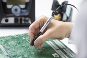 materials to meet it for high-reliability and safety-first automotive electronics. New materials, equipment, tools, and processes are emerging for electronic advanced component packages, printed circuit board (PCB) fabrication and electronic assembly. Automotive electronics assemblers must consider not only the thermal impact, but also signal propagation and integrity in automotive electronic designs. These challenges demand a higher level of thermal control and traceability from all equipment, including the hand soldering and rework tools. It also dictates possible automation of traditionally manual hand soldering and rework processes with robotic soldering and more automated rework.
Advanced component packaging includes die attachment to component substrate with conductive adhesive (silver hybrid) to efficiently dissipate heat into components, capacitate switches, antenna on package (AoP), EMI shields built on component epoxy package.
PCB fabrication materials and processes are using unique low-loss dielectric substrates and conductor surface finishes that enhance RF propagation and reduce insertion loss, conductive/copper-filled vias for additional thermal dissipation and designs preventing cross talk. New processes for electroless copper that increase elongation properties from 2-4% to 12-16% that may allow for formable circuits on plastics and other materials.
PCB assembly solder paste/enhanced alloys like Innolot, a (SAC) with small amounts of Antimony, Bismuth and Nickel, is creep resistant with tensile strength able to withstand the high operating temperatures of the automobile. Processes like underfilling components are being added for additional mechanical strength. Conformal coating application is being used to protect electronics from elements as well as provide mechanical strength.
What environmental stress tests should be prescribed and how many cycles endured to ensure reliability and safety quality results since the automotive service environment is very harsh? We have under-the-hood temperatures that may exceed 140°C with the low temperatures near -40°C, constant vibration, moisture, spray, dust, and salts. New materials are being introduced to mitigate some of these environmental stresses such as new alloys that enhance creep properties (reduce thermal fatigue solder fractures) and plastic combinations that have compatible coefficient of thermal expansion (CTE) properties to reduce cracked plastic components. Depending on the automobile electronic system, the environmental thermal stress testing could range from 1000-3000 cycles. For example, the ADAS may undergo 3000 thermal test cycles from -40°C to 125°C.
Where are automotive electronics going? Naturally, flex circuits will reduce the weight of current cable/wiring systems. New types of interconnections that are more reliable. Molded Interconnect devices (MID) where the mechanical meets electronics. These MID mechatronic devices are the joining of electrical and mechanical engineering that will increase functionality and reduce both weight and space. Lenora states we will become an occupant instead of a driver in the future.
It is not a surprise that IPC has moved into the realm of automotive electronics. We now have an automotive electronics workmanship and acceptability document, IPC J-STD-001GA/ IPC-A-610GA Automotive Addendum to IPC J-STD-001G Requirements for Soldered Electrical and Electronic Assemblies and IPC-A-610G Acceptability of Electronic Assemblies (published 3/20). What was eye opening in this addendum is the new acceptability criteria for various new component packages used in automotive electronics. A fabrication qualification standard for automotive bare boards, published on 12/2018, is titled IPC-6012DA-WAM1, Automotive Applications Addendum to IPC-6012D, Qualification and Performance Specification for Rigid Printed Boards. Also, the IPC/WHMA-A-620, Requirements and Acceptance for Cable and Wire Harness Assemblies may get an automotive addendum in the near future.
The future of rework and repair techniques on automotive nonconforming material should remain the same during the OEM process. As previously mentioned, be sure to have the latest technology soldering/rework equipment with a wide range of tip geometries and active sensing closed-loop temperature control and traceability may be necessary. The cheap old solder station with three tips just doesn’t cut it in the high-tech, high-demand automotive market Although, the challenge of proper rework and repair on automotive electronic assemblies and cable harnesses that fail operationally after vehicle purchase is very limited. Proper repairs made on vehicles could be a 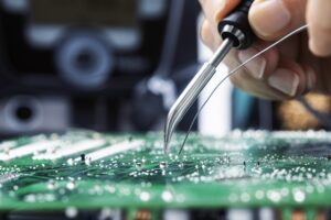 critical safety and reliability concern. Most automotive PCB assemblies are considered the lowest replaceable unit; the whole board and potentially related integrated mechanical assembly will be replaced, whether it is a simple fix (i.e. moisture/condensation on connector interface) or a more complex component failure. Additionally, boards are frequently conformal coated, encapsulated or potted, making them difficult to repair. However; after-market simple plated through-hole circuit boards that are not coated could be repaired easily, especially if the defect is conspicuous.
Electrical wiring failures can be an insidious troubleshooting process for auto mechanics. Automotive wire harnesses that fail operationally may be reterminated or spliced. Occasionally, cable harnesses are completely replaced, depending on job complexity, time, and alternative repair methods available. If there is an open on a particular wire, mechanics frequently will overlay a new wire and splice that bypass wire in place. When connectors are broken or damaged, mechanics may replace with a connector pigtail if available and splice wires in place. Mostly rudimentary butt crimp splices will be used to repair wire damage. If soldering is needed, a butane iron likely will be used. If flexible circuits/cables become prevalent in future automotive wiring, it will become even more difficult and expensive to repair a vehicle. Replacement of connectorized modular flex cables will occur.
Traditionally, auto mechanics are not trained in printed circuit assembly repairs or proper soldering and crimping techniques. Andrew Jones, a certified ASE Master Auto Mechanic who works in fleet service, also maintains a J-STD-001 certification. Since he is an automotive electronics expert, he has provided significant insight into the typical electrical auto repairs executed in the shop. Additionally, I reviewed General Motors and ASE certification electronic and electrical training manuals and found that the repair techniques prescribed are not as detailed as 7711/7721. Little consideration is given to the level of conformance of repair. Also, inspection of automotive repair is rarely required or used as a control mechanism. Test is the validation of functionality. The quality of workmanship is not monitored. Moving into the future, reliable repairs should be a priority to maintain safety features and protect vehicle occupants. State and federal government agencies may regulate auto repairs in the future for driverless vehicles. Looking ahead the IPC and WHMA may develop an appropriate training program for auto mechanics that probe deeper into relevant soldering techniques, crimp splice techniques, cable/wiring harnessing, and basic inspection methods for automotive electronics repair.
Automotive electronics have come a long way. Forty years ago, there were no electronics in any automobiles, while today they operate almost completely using electronic technologies. To continue making automobiles as safe and feature-rich as possible, automotive electronics must operate with a new range of complex signals that can process in consistently harsh environments. New equipment, tools, materials and processes are needed for advanced component packages, PCB fabrication and electronic assembly. Automotive electronics assemblers must consider not only the thermal impact, but also signal propagation and integrity in automotive electronic designs. These challenges demand a higher level of thermal control and traceability from all equipment, including the hand soldering and rework tools.
Circuit Technology, Inc. can provide top-notch training when the new training material becomes available for IPC J-STD-001GA/IPC-A-610GA Automotive Addendum. Evamaria Jones is a
MIT J-STD-001/MIT IPC-A-610/CIT IPC-A-620/CIT 7711&7721/CID Certified Interconnect Designer with more than 35 years’ experience in electronics.