BTU Vacuum reflow oven operation
Vacuum reflow has been around for quite some time with only slight interest but it is now gaining attention (Popularity) in the electronic assembly industry because of a desire to lower and even eliminate voids in solder joints and thermal pads.
Initially vacuum reflow was a batch operation where boards were placed in a vacuum chamber and heated to melt the solder. During the heating process the chamber was evacuated and the void level was reduced or, in some cases, removed from the solder joint. Sometimes the vacuum was applied when the solder approached the liquidus and at other times vacuum was applied during the complete heating cycle. The equipment was expensive to purchase and operate but the biggest detriment was low throughput, therefore vacuum reflow was not appropriate for high volume production. Additionally there were questions about the need to eliminate voids, with some claiming that a small number of voids in joints actually increased their apparent strength.
There was little motivation to pursue vacuum reflow until the need to dissipate heat from high power components (especially automotive under-hood components) came upon the scene. At first vias seemed to be part of the answer but it was impossible to guarantee that a via would be under the “hot spot” in the component, therefore low or no voids in the thermal pads seemed to be the answer.
Today “low voids” can mean anything from 20% to zero with numerous people saying that 5% is the desired realistic limit. The question became; How do we get from the current 40% plus voids in thermal pads to 20% and below with high volume production equipment? Solder paste and thermal profile modifications have helped but being consistently below 5% is a stretch.
The answer is a continuous vacuum assisted reflow oven, where a vacuum chamber is placed between the last heated zone and the cooler in a standard convection reflow oven. This presents material, and engineering design challenges because the board has to be transported into and out of the chamber, the vacuum section has to seal, and vacuum needs to be applied, at elevated temperatures. There are numerous designs currently being used for the internal vacuum chamber that use entrance and exit doors or bell jar configurations. Doors tend to be lightweight and move easily while the bell jar design makes access to the conveyor system inside the chamber simple. The transport system presents issues because the edge rails have to be interrupted for the door or bell to seal and the board has to stop in the chamber while vacuum is being applied. In each case the seal material has to withstand temperatures approaching 350°C.
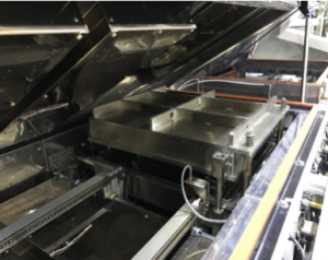
Bell Jar Design Vacuum chamber
 This brings us to the process steps encountered in a continuous vacuum reflow system. The initial heating is exactly like a normal reflow oven where convection rate, zone set points and belt speed are the factors in heating the board. Once the board begins to enter the vacuum chamber we lose the power of convection to heat the board and rely on radiation for continued heating.
When the board is in the vacuum chamber, 4 things are controlled – pump down rate, vacuum level, vacuum hold time, and equalization rate.
Pump down rate –The speed at which the vacuum is applied. If it is too fast the voids can explode as they leave the joint or pad and produce solder balls or splatter. If it is too slow we waste time and the time above liquidus (TAL) is extended.
Vacuum level – The amount of vacuum the board is exposed to. Levels as low as 1 Torr and high as 250 Torr (and higher) are possible. But even with a very large vacuum pump it takes longer to go to low vacuum levels.
Vacuum hold time – The time the board is exposed to the vacuum level selected. Hold times can be as short is a second or as long as a few minutes. At 1 second there is little time for the voids to exit and greater than 40 seconds have proven to be not needed.
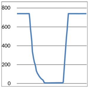
5 Torr, 40 sec hold w/ controlled pump down
Equalization rate – The speed at which the vacuum is released and the chamber returned to atmospheric pressure. Currently there is no known adverse effect with high equalization rates. But it does take more time to reach atmospheric pressure with low vacuum levels.
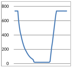
20 Torr, 30 sec hold w/ controlled pump down
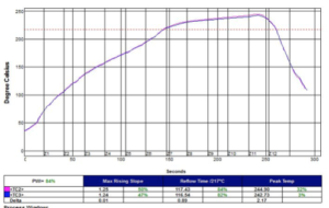
The total time for the vacuum portion of the reflow profile includes the four items listed above plus the time to transport the board in and out of the chamber. The following two thermal profiles (conducted at the Universal Advanced Process Lab with the BTU vacuum test board) show the effect of changing the vacuum hold time on the TAL at 20 Torr. A 10 second hold results in a TAL of 87 seconds and a 40 second hold results in a TAL of 117 – a 30 second difference. Therefore, there is a 1 to 1 relationship between hold time and TAL differences.
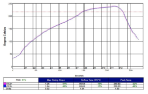 If we change the vacuum level from 20 Torr to 60 Torr and maintain a 40 second hold we get a TAL of 106 seconds. This 11 second difference (117 – 106) is due to the softer vacuum requiring less pump down and equalization time.
Each of these factors has a significant effect on the TAL and a slight effect on peak temperature due to being in the heat longer. In the two cases of 20 torr with 10 and 40 seconds holds mentioned earlier, the peak temperature changed by about 4°C. This emphasizes the need to profile boards when any changes to the vacuum cycle or level are made. Thermal profiling is difficult in vacuum systems because the TC wires are not compatible with the vacuum chamber a seal. Currently the profiler has to be in the chamber during the vacuum cycle but alternatives methods are being evaluated.
Vacuum Trial Results
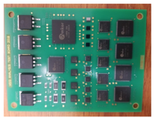
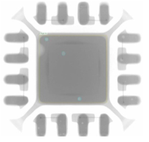
Mike Meilunas from the Advanced Process Laboratory at Universal Instruments, with assistance from BTU, developed a test board for void studies. The board included QFNs/MLFs with various sized thermal pads, resistors, and D2PAKs. A study was designed to evaluate the affect of vacuum levels and hold times on voids with SAC 305 solder paste from numerous suppliers, two board finishes, and various screen configurations.
 A ramp to peak thermal profile with a linear heating rate of 2°C/ sec and a peak temperature of 240°C was developed. Various levels of vacuum hold times, and pump down rates were evaluated
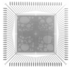
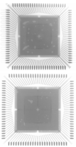
Xray images of MFL 100
no vacuum, 120, and 20 Torr
X-ray analysis shows that pad size, vacuum level, and hold times affect the void level in the thermal pads. The following-ray images of MFL 100, 52 and 16 show the effect of processing without vacuum, and processing with 120 and 20 Torr with a 20 second hold
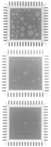
Xray images of MFL 52
no vacuum, 120, and 20 Torr
Xray images of MFL 16
no vacuum, 120, and 20 Torr
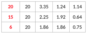
The following charts show the effect of various hold times at 20 Torr and vacuum levels
Effect of hold time on void % at 20 tor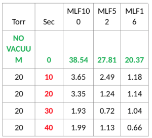
Effect of vacuum level on void % with a 20 sec hold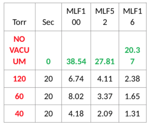
 Unintended Consequences
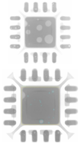
It is interesting to note that we found an issue with fine pitched CSPs when they are subjected to hard vacuum levels. Voids in the balls combine and instead of escaping to the surface they expand the ball. When the balls make contact each other, they can stay in contact (stick) and cause bridging or shorts between circuits as shown below. We discovered that dipping the CSPs in flux elevated the issue.
X-ray image of fine pitch CSP bridging
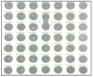
20 Torr held for 20 seconds
Something to Consider
Although the industry is focused on the % voids in thermal pads the real issue may be the location and size of the voids. With this in mind, Mike Meilunas of the APL analyzed the voids size distribution on QFN100’s at various vacuum levels and found that once we got below 120 torr the odds of having a void that is > 15 is very small.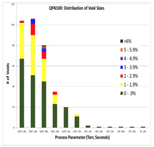
Conclusions
The results of this trial shows that vacuum reflow is an excellent way to decrease the void level in thermal pads of MFLs. Levels below 5% were obtained with hold times of 20 seconds and vacuum levels of 20 torr. Additionally, it was a surprise to learn that relatively soft vacuum levels of 120 torr and `short hold times can significantly lower void levels.
Fine pitch components may need special handling.
Acknowledgements
Michael Meilunas, Universal Instrument Corporation needs to be thanked for his help in designing the board, collaboration in determining the experiments and running the trials. Also Arvind Srinivasan Karthikeyan, Auburn University for running the trials and analyzing the void level in the many solder joints.
Portions of this paper were originally published in the proceeding of SMTA International Rosemount IL, October 14 –October 18, 2018
Additional papers describing results of trials conducted on the BTU vacuum oven while it was at the APL were published in the proceedings of SMTA International 2019
Vacuum Reflow Processing of Ball Grid Array Packages for reduced Solder Joint Voiding and Improved Attachment reliability
By Richard Coyle Ph.D. Nokia Labs et al
Effect of Vacuum Reflow on Solder Joint Voiding in Bumped Components
By Arvind Srinivasan Karthikeyan, Auburn University et al.